
The power converter is rated for 350W continuous operation with peak power handling capability of 500W. And an auxiliary power supply board was used in our system to generate +12V and +5V, to provide bias supply for the control circuitry of our power converter. The auxiliary power supply is supplied from the battery pack and this power supply is rated for operation with 9V-36V input which covers the range of battery pack voltage.
The following image shows the power converter structure and its control architecture.

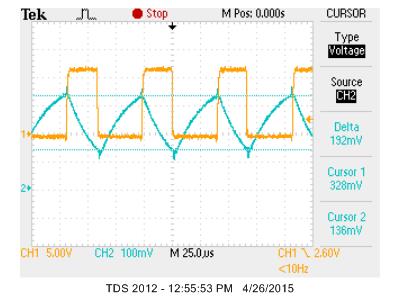
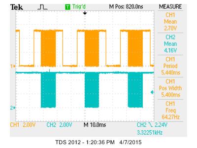
The 3-Φ inverter control is done in a different fashion. Hysteresis control technique is employed to control the motor phase current(s). The current reference is derived from the throttle and brake input, based on the algorithm written in the microcontroller. When the bike needs to accelerate, a positive current reference is generated and when it's needed to brake, a negative current reference is generated. The actual motor current is compared with the set current reference to regulate it within a current ripple band of 2A. The hysteresis comparator circuit is tested separately with a R-L load before driving the motor. The following figure shows the result of this test. For this test, the inverter was supplied with external 50V source and phase C of the inverter was used to drive the R (13Ω) - L (90μH) load which was connected across the switching node of phase C and ground of DC bus. The hysteresis band control resistor was adjusted to have 2A pk-pk current ripple.
The circuit board developed also has few protections in-built. We have boost output over-voltage protection set at 60V and under-voltage protection set at 38V, with a hysteresis band of 5V, for each of them. Similarly, we have boost over-current protection set at +24A and -8.5A, with a hysteresis band of 3A. These protection circuits were tested for functionality and were adjusted wherever required, before doing any power test on the converter. The under-voltage protection disables the inverter alone whereas all other faults disable the boost converter. In addition to above active protections, few passive protections are implemented in the power converter such as fuse, NTC at battery input, fuse at inverter output, TVS and MOV at boost output (to restrict over-voltage during regenerative braking) and TVS at external signals interfacing the board.
In the course of testing, the control circuitry were tested first and different set points were adjusted, wherever required. Then the protection circuits were tested for their functionality. Next, the boost converter was tested, with 24V from a regulated power source, in open loop and the load was gradually increased to 330W to check that power circuit is good. Then the current loop of the converter was tested, followed by voltage loop testing, for both steady state stability and transient response. Again, the boost load was increased upto 330W for testing the closed loop boost converter. In this phase of testing, inverter circuit was made non-operational.
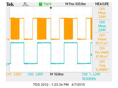
In the second stage of testing, the boost converter was permanently disabled and the inverter was supplied with 50V, from an external power supply. Then the hysteresis comparator was given with a triangular reference signal of 10kHz, from function generator, oscillating around 2.5V, since the current sensors provide 2.5V output when the current through it is zero. This way we generated the PWM signal for different phases. Next, the wheel position was manually adjusted to pass the PWM signals, from the output of hysteresis comparator, to the inverter gate driver, one phase at a time. Then the Gate to ground signals of both top and bottom MOSFETs were checked to ensure there is sufficient dead-time between them. Then, each leg of the inverter was loaded with R-L load (as mentioned earlier) and tested for 100W load and thus ensuring that the power circuit of the inverter is okay. And after passing all the test, the inverter output was connected to the motor and then the motor was spun with reference signal coming from the throttle of the bike. The braking operation was also tested at this stage.
In third stage of testing, the boost converter and the inverter were integrated together along with the auxiliary power supply. The microcontroller was also coded with the required algorithm and was used for testing in this phase. The input of the converter was supplied from 24V external power supply and then we started the boost operation by changing the 3 position switch from position 1 to position 2. Next, we changed the switch position to position 3 and inverter stage was enabled. Then the throttle was rolled to run the bike wheel and consecutively the 2-stage braking was tested. In this stage of testing, the input power supply was also connected to a resistive load, in series with a diode to allow regenerative braking. The power supply current limit was set to 6A initially which was later increased to 30A, to check everything is okay, before connecting it to the battery pack.
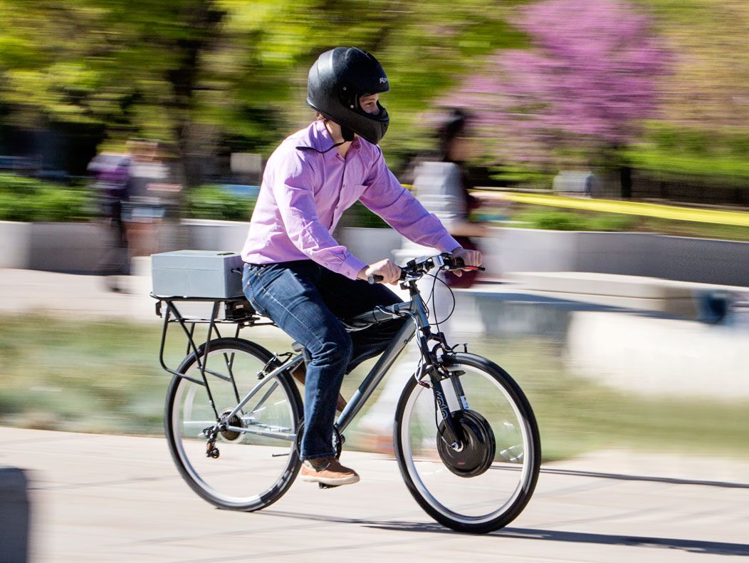
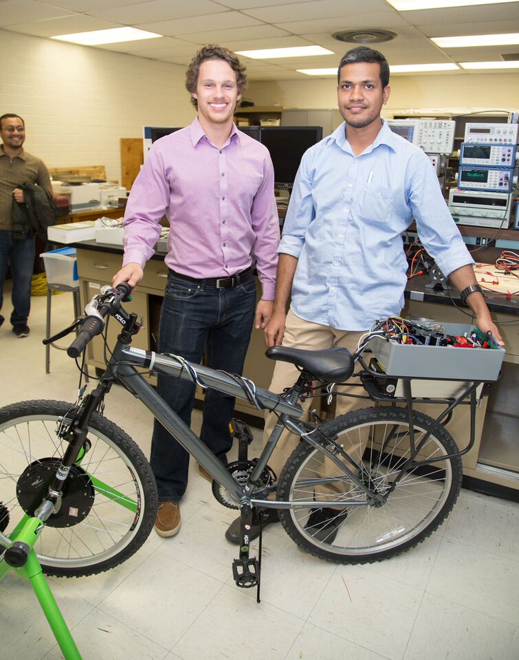
Finally the entire converter system was connected between the battery and the motor and acceleration and braking tests of the wheel were done. And then the bike was taken for a ride for a road test. Final adjustments were done on the maximum positive and negative motor current reference, after the road test. The following figure shows the result during regenerative braking. The bike was mounted on a trainer with load. It can be seen that the battery current goes negative confirming regenerative braking. Since the inertia of the bike is less and load resistance (offered by the trainer) was high, we are only able to get a little amount of energy. But, in real road-ride scenario, the overall inertia of the system will be high and regenerative braking will fetch more energy back to the battery.


Our initial plan for the Automated Bartender was to use the original alcohol bottle and invert it on a ring. We were going to rotate the entire ring of bottle above a single cup on a pressure plate. The pressure plate was to work as our cup detector. We had an issue with this setup. The motor would have had to have been a much larger and stronger motor in order to rotate all the bottles and liquid. We also ran into a much larger issue that ended up being the main reason for our switch to the current setup. The bottles when inverted had no way to release the pressure from the vacuum induced by the release of the alcohol.
In an attempt to address this issue we took many approaches. The initial idea was to find a fitting to attach the bottles threaded end to the threading on the flow sensor. In our research we were unable to find such a fitting. We attempted to make our own fittings by using a liquid pourer used in many bars. An issue that arose through this method was the pressure release method in the pourer only functioned at a 45 degree angle and for short amounts of time. This would only allow the bottle to go to that angle and would need to be re-tipped for each ounce required. For this reason, this method was ruled out.
From this method, we wend with a peristaltic pump method. The bottle would be able to sit upright with tubing fed in. The pump would then suck the desired amount out of the bottle and deliver it to the cup. The peristaltic pump has very accurate measurements. This would have eliminated our need for the flow sensors. The downside to the pump was that it was incredibly slow. A single cup would have taken over minute to fill. For this reason, we eliminated this method
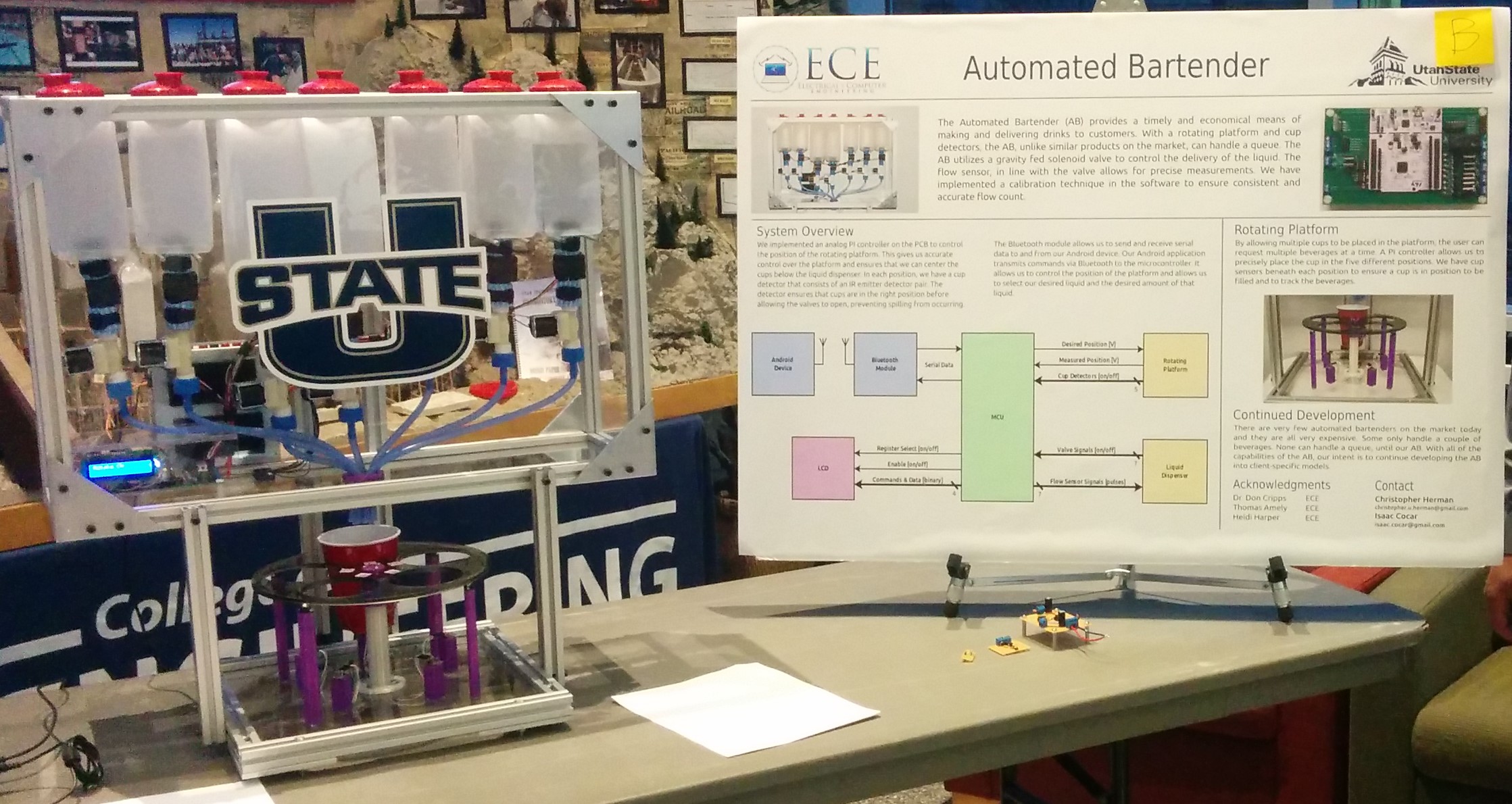
To get to our current set up, we went through all these stages. We knew we could not use the original bottles. We knew we would need to use some sort of sensor for feedback of the amount of liquid that has passed through. We also decided that in order to obtain our desired queue we would need to have a rotating platform opposed to a rotating dispensing system.
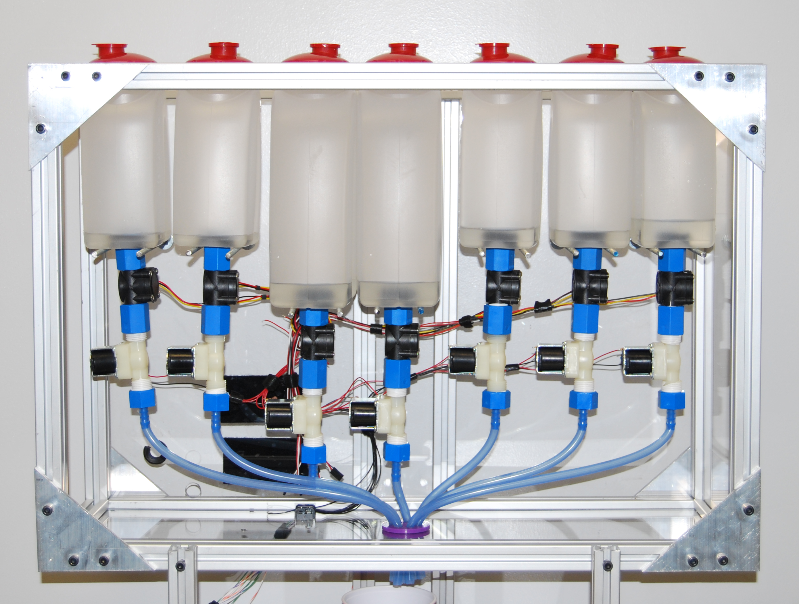
On our current set up we are using liquid containers that we have drilled a hole through the bottom allowing a male threaded adapter to be our feed unit, and allows a female of same thread to be on the bottom side of the container to thread onto the male, attaching the feed unit to the flow sensor. Here we have had issues also. This issue is that we have leaking issues. Using o-rings the bottles leak plenty when filled with water. A solution we have come up with is using cork sheets. We cut the cork sheet to create gaskets. This has essentially cut out the leaking, with minor drips occurring over the period of a few days.
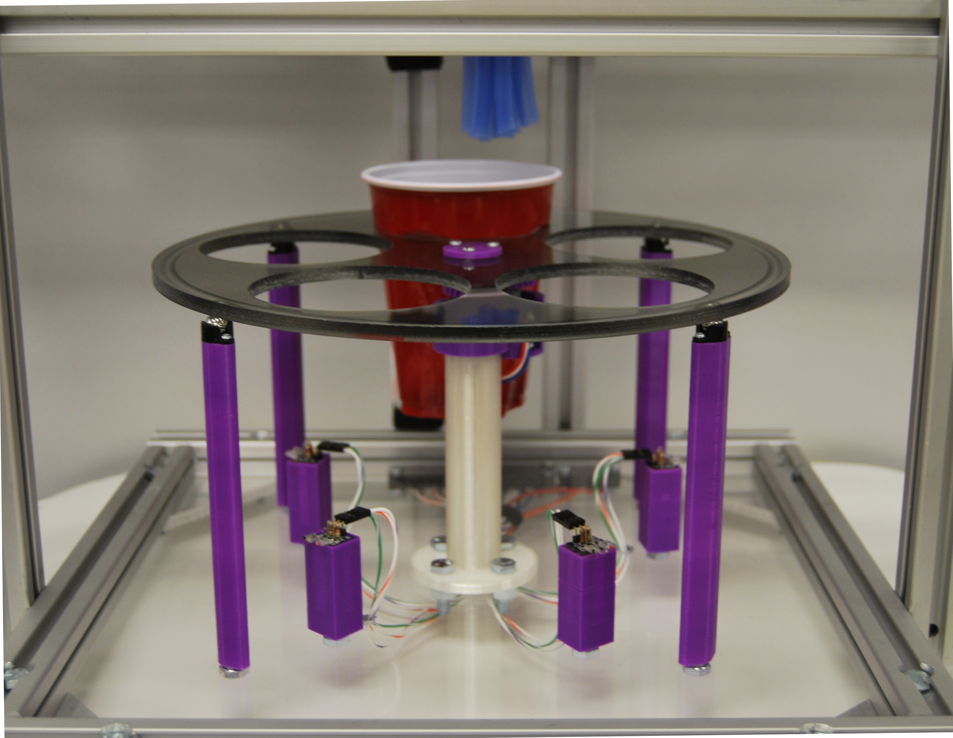
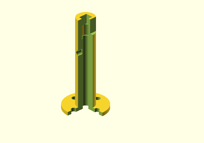
On our rotating platform we also have had a few issues. The original motors we were going to use were rated to handle our full load, however in testing they burnt out very quickly. We went through two of these motors before arriving at our current motor. On the rotating platform we were also using hand crafted and tooled engine mounts, potentiometer mounts, and supports. This gave us minor clearance issues and stability issues. In order to fix this we 3-d printed a new motor mount, a potentiometer mount to fit on the motor mount, new supports, and new gears.
Our current dispensing set-up consists of five 1000mL containers, two 1500mL containers, seven flow sensors, seven gravity-fed valves and all appropriate fittings and adapters. The flow sensors are positioned between the container and the valve. This set-up gives us an accurate flow count.

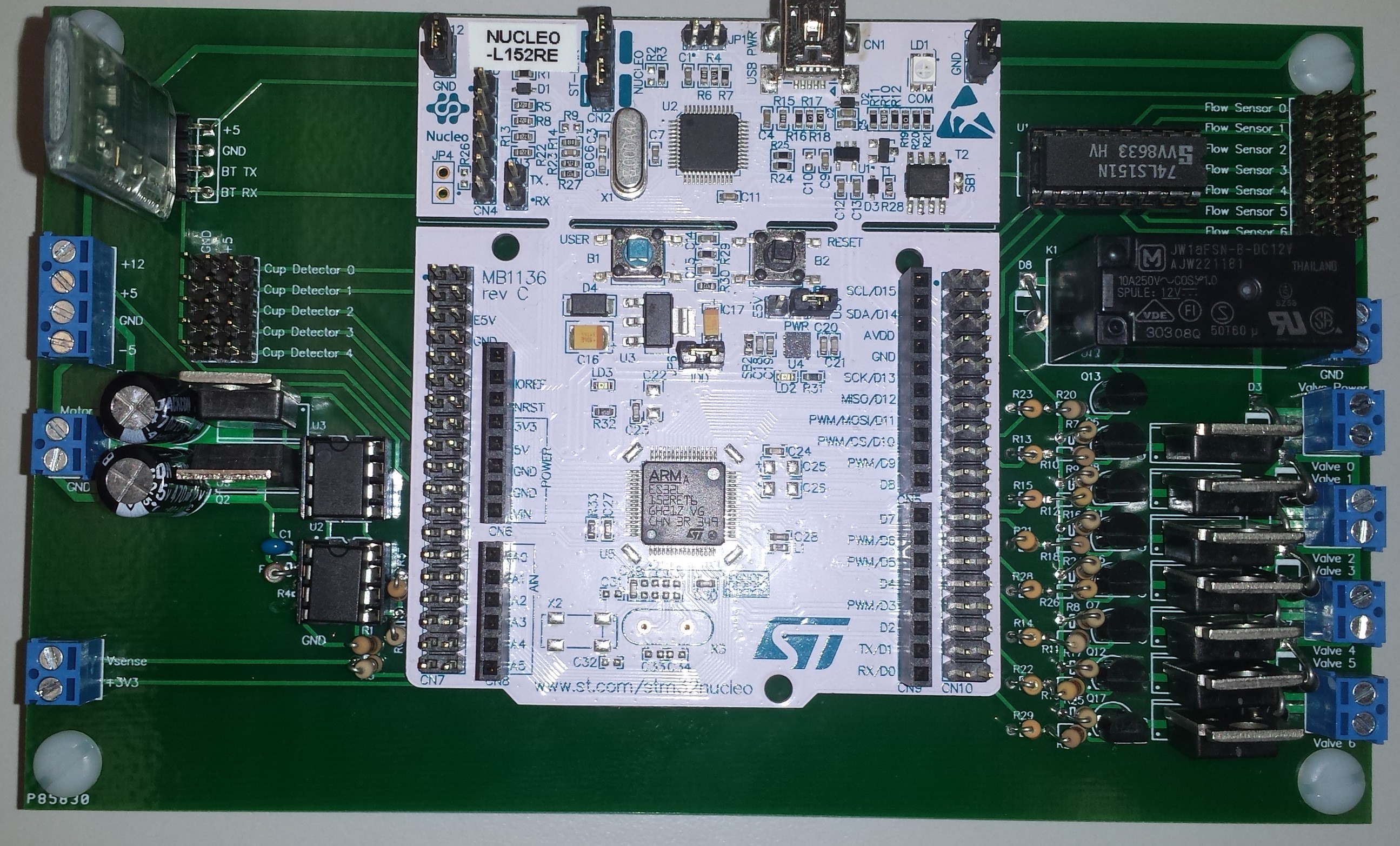

We did not quite reach the desired low budget cost that we were desiring. This current cost that we have shown is using prototyping materials as apposed to a mass production type product. We would not need to use a development microcontroller, and instead could use much cheaper pre-programmed chips. We have also eliminated the need for a touchscreen HMI on the enclosure with the development of our android application. This greatly reduces the cost of the product. Other items when purchased in bulk for mass production would also greatly reduce the cost.